Designing a Shell and Tube Heat Exchanger (STHE)
Introduction:
For effective heat transfer between two fluids while maintaining their separation, STHE are widely utilised in a variety of industries. They are appropriate for high-temperature and high-pressure applications because they are durable and adaptable. To ensure maximum performance and safety, STHE design entails a number of crucial processes. We’ll look at the key components of STHE design.

Understanding the Basics
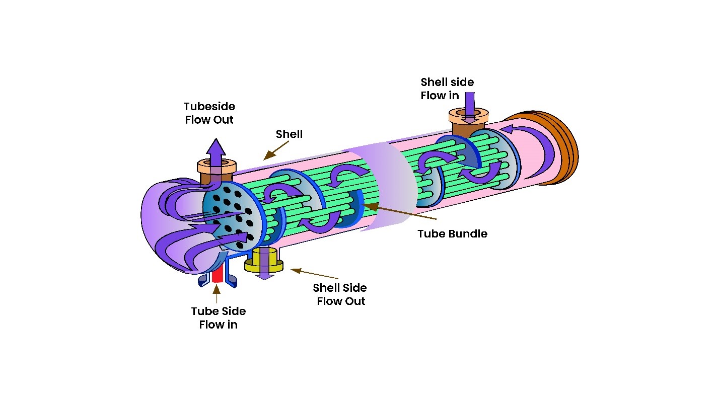
Before commencing the design process, it is crucial to have a firm grasp of the foundations of shell and tube heat exchangers. These devices feature a cylindrical casing with many tubes inside. A tube-side fluid is one that flows inside the tubes, whereas a shell-side fluid is one that flows around the tubes. The heat of one fluid is transferred to the other through the tube walls. A shell and tube heat exchanger is defined by many factors, including the tube diameter, tube length, shell diameter, tube arrangement, and many more.
Design Steps
- Determine the Heat Exchanger’s Purpose
Establishing the goal of the heat exchanger is the first stage in constructing a STHE. What particular heat transfer requirements does your application have? Is a fluid being heated or cooled? What are the required temperatures and pressures for the fluids on the shell side and the tube side? A good design depends on your ability to comprehend the objectives and limitations of your heat exchanger. - Selection of Materials
Choosing the appropriate materials for the heat exchanger’s shell, tubes, and other parts is essential. Materials are chosen based on a variety of criteria, including corrosion resistance, temperature and pressure requirements, and the characteristics of the fluids being handled. STHE are often made of carbon steel, stainless steel, or an assortment of alloys. - Determine Heat Transfer Area
In order to determine how much heat transfer area a heat exchanger will need, it is necessary to know both the heat transfer rate and the temperature difference between the two fluids. The area of heat transmission can be calculated with the help of the following formula:Q = U * A * ΔTlm
Q = rate of heat exchange (in watts or British thermal units per hour).
U = total heat transfer coefficient (in W/m²·K or BTU/hr·ft²·°F).
A = area of heat exchange (in square metres or square feet).
ΔTlm = average temperature gradient as a logarithm (in Kelvin or Fahrenheit). - Tube Layout and Geometry
The heat exchanger’s efficiency is tremendously affected by the tubes’ geometry and layout. There are a lot of options to consider while designing a tube, including the tube’s diameter, length, pitch, and number of passes. While longer tubes with smaller diameters can improve heat transfer efficiency, they may also result in larger pressure drops. The shell-side fluid flow is influenced by the tube pitch, or the distance between the tubes. - Calculate the Required Number of Tubes
The intended heat transfer rate and the tube-side fluid flow rate determine how many tubes are needed in the heat exchanger. You can use the following formula to determine how many tubes are needed:N = Q / U A ΔTlm
N = the number of tubes.
Q = heat – transfer rate.
U = heat transfer coefficient.
A = area of heat exchange.
ΔTlm = logarithmic mean temperature difference - Sizing the Shell
A number of variables, including the size and quantity of tubes, fluid flow rates at the shell’s side, and the required pressure drop, affect the shell’s dimensions, including its length and diameter. The diameter of the shell ought to permit sufficient fluid movement while leaving sufficient room for the tubes. - Estimation of Pressure Drop
Appropriate design requires an estimation of the pressure drop on the shell-side as well as the tube-side. Pressure drop has an impact on the heat exchanger’s effectiveness and performance. Calculations of pressure decreases consider variables such as fluid characteristics, tube configuration, and flow rates. - Baffle Design
Baffles are installed inside the shell to provide better heat transfer and direct fluid flow. The spacing and design of baffles is critical to achieving the desired heat transfer efficiency while minimising pressure and drop. Depending on the purpose, different baffle configurations, including segmental or helical baffles, might be employed. - Determining the Overall Heat Transfer Coefficient
The overall heat transfer coefficient plays a significant role in heat exchanger design (U). Heat-transfer resistance on both the shell and tube sides is calculated. Empirical correlations can be used to determine U, a variable that is material- and design-specific to heat exchangers. - Consideration of Fouling and Maintenance
Over time, fouling the buildup of deposits on the heat exchanger’s surfaces can cause it to lose efficiency. When choosing materials and calculating the heat transfer area, designers must take fouling into consideration. The heat exchanger should also be made with simple maintenance in mind, which could entail the use of detachable tube bundles. - Thermal Expansion
When constructing a shell and tube heat exchanger, take thermal expansion into account. Temperature variations may cause the materials to expand or contract at different rates. The heat exchanger structure may experience stress as a result, which needs to be controlled to prolong the life of the system.
Computer-Aided Design (CAD) and Simulation
Simulation tools and computer-aided design (CAD) software can be very helpful in the design process. By modelling and analysing the heat exchanger’s performance under various scenarios, engineers can use these techniques to optimise the heat exchanger’s design for both economy and efficiency.
Safety and Regulatory Compliance
Ensuring adherence to safety norms and regulations is a crucial aspect of designing a STHE. The industry and application may cause these standards to change. For the heat exchanger to operate safely, it is imperative that it is made to endure the pressure, temperature, and climatic conditions that are stipulated.
Summary
A thorough understanding of fluid dynamics, engineering, materials science, and heat transfer concepts is necessary for the intricate process of designing a STHE. An effective heat exchanger is an essential part of many industrial processes because it can have a big impact on system performance and energy efficiency.
At Waterman Engineers Australia, we serve a variety of sectors with our expertise in the design, manufacture, and installation of STHE. We can help you whether you work in the oil and gas, petrochemical, fertiliser, speciality chemical, compressor, or FPSO (Floating Production Storage and Offloading) industries.

Our experience encompasses both tiny units, under 5 m², and large heat exchangers, up to 7500 m². From 6″ pipes to about 2.5 metres, we provide a wide range of shell diameters and tube lengths up to 13.5 metres. Among the TEMA types that we are familiar with are BEM, AES, AET, AEU, AEW, BEP, AKU, DEU, CEU, AFU, NEN, BJ21S, BJ12U, CKU, and others.
We have several different types of process exchangers in our portfolio, such as electric heaters, hairpin, falling film, continuous fin, reboilers, condensers, and coolers. With a dedication to quality and in-depth knowledge of heat exchanger design, we are your reliable partner in guaranteeing effective heat transfer for your particular industrial requirements.
For all of your shell and tube heat exchanger needs, get in touch with Waterman Engineers Australia, and let us assist you maximise your heat transfer procedures.


