Corrugated Plate Interceptor (CPI)
1. What is a Corrugated Plate Interceptor (CPI)?
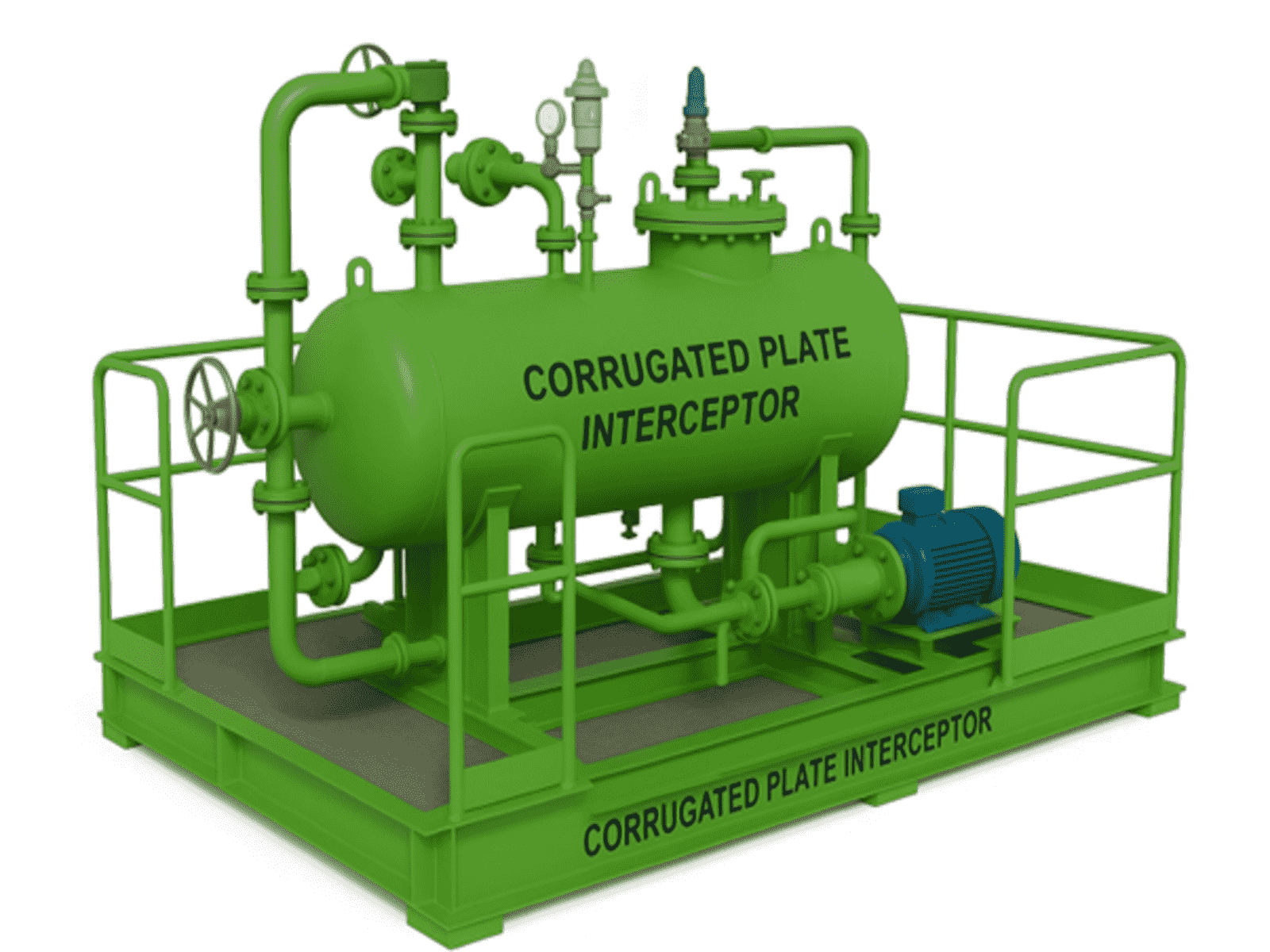
A CPI separator is a compact, enhanced gravity oil–water separator that uses closely spaced, inclined, corrugated plates to accelerate the separation of immiscible liquids (oil and water) and sometimes solids.
- The design increases the effective settling/separation area while reducing the footprint compared to a conventional API separator.
- CPI is widely used in produced water treatment, refinery wastewater, and industrial oily water systems.
Basic principle:
- Oil droplets rise (due to density difference) and coalesce on the underside of inclined plates.
- Solids settle on the top side of plates and slide down to a sludge hopper.
- Clean water exits at the bottom or side outlet.
2. How CPI Works to Reduce Oil Content
- Flow Distribution
- The oily water enters the CPI through a feed inlet with baffles to evenly distribute the flow and reduce turbulence.
- Separation Mechanism
- Oil Phase: Oil droplets attach to the underside of inclined corrugated plates and move upwards along the plate surfaces. As droplets meet, they merge (coalesce), forming larger droplets that rise more quickly to the surface, forming an oil layer that is skimmed off.
- Water Phase: The clarified water moves downward, exiting through the bottom outlet.
- Solids Phase: Suspended solids settle on the top side of the plates and slide downward to a sludge hopper.
- Enhanced Efficiency
- By using multiple inclined plates, the separation path for oil droplets is shortened, and the settling/rising surface area is multiplied — improving oil removal efficiency compared to plain sedimentation tanks.
- Performance Targets
- Inlet oil content: Typically up to 200–500 ppm.
- Outlet oil content: Commonly <50 ppm; high-quality CPI designs can achieve <10–15 ppm depending on inlet droplet size.
- Typical droplet removal size: ≥60 microns (API spec) down to 30 microns for enhanced designs.
3. Uses & Applications of CPI Separators
A. Oil & Gas Industry
- Produced Water Treatment (onshore & offshore)
- Pre-treatment before polishing units (hydrocyclones, walnut shell filters, or membrane systems).
- Common in offshore platforms where space is limited but high efficiency is needed.
- Refinery Wastewater Treatment
- Removal of oil from desalter effluent, tank bottom drains, and oily stormwater.
B. Petrochemical & Chemical Processing
- Treatment of process condensates contaminated with lubricants, solvents, or product oils.
- Pre-treatment before biological wastewater treatment systems to prevent oil overload.
C. Power Plants
- Removal of turbine lube oil from cooling water or boiler blowdown streams.
- Treatment of oily drains from turbine halls.
D. Marine Applications
- Treatment of machinery space bilge water before discharge.
- Often paired with polishing units to meet IMO 15 ppm discharge standard.
E. Mining & Heavy Industry
- Wash bay water treatment for heavy equipment.
- Removal of flotation oils from ore processing water.
F. Airports & Transportation Hubs
- Oily stormwater treatment from aprons, fueling areas, and maintenance hangars.
- Recovery of spilled fuels and lubricants from drainage systems.
4. Advantages of CPI Separators
- Compact Footprint: Requires less space than API separators for the same flow capacity.
- Low Energy Use: Gravity-driven; no moving parts in the separation zone.
- High Separation Efficiency: Can remove droplets smaller than those separable by conventional tanks.
- Ease of Maintenance: Plates can be removed for cleaning if fouled.
- Modular Design: Multiple plate packs can be fitted in parallel to handle higher flows.
5. Limitations
- Sensitive to Solids Overload: High suspended solids can clog plate packs, requiring upstream strainers or grit removal.
- Limited for Emulsions: Stable oil–water emulsions require chemical breaking or heating before CPI.
- Flow Distribution Critical: Uneven flow or turbulence reduces performance.
6. Typical Position in Process
- CPI is usually secondary separation after coarse gravity separation or skim tanks.
- Often followed by a polishing stage like:
- Induced Gas Flotation (IGF)
- Dissolved Air Flotation (DAF)
- Coalescer filters
- Multimedia filtration or walnut shell filters
Corrugated Plate Interceptor (CPI) – Technical Datasheet
1. General Information
| Item | Specification |
| Type | Corrugated Plate Interceptor (CPI) |
| Application | Removal of free and dispersed oil from oily wastewater |
| Design Standard | API 421, ASME Section VIII Div. 1 (for pressure vessels if applicable) |
| Design Life | 20 years minimum |
| Performance Guarantee | Outlet oil content ≤ 15 ppm (free oil) for droplets ≥ 30–60 μm |
2. Process Data
| Parameter | Design | Normal | Maximum |
| Flowrate | ______ m³/hr | ______ | ______ |
| Inlet Oil Content | 200–500 ppm | ||
| Outlet Oil Content | ≤ 15 ppm | ||
| Droplet Size Removal | ≥ 30 μm | ||
| Fluid Temperature | 30°C | 80°C | |
| Operating Pressure | Atmospheric (standard), or as specified | ||
| Design Pressure | 0.5 bar(g) (if vented) or per specification | ||
| pH Range | 6–9 | ||
| Density | Water: 1000 kg/m³; Oil: 850 kg/m³ |
3. Mechanical Design
| Item | Specification |
| Vessel Type | Horizontal rectangular or cylindrical |
| Material of Construction | SS316L (corrosion resistant) or coated CS |
| Plate Material | FRP, PVC, or SS316L (oil-resistant, smooth surface) |
| Plate Angle | 45° inclination |
| Plate Spacing | 20–50 mm |
| Plate Pack Removal | Removable for cleaning |
| Oil Collection | Skimming trough or pipe |
| Sludge Collection | Hopper bottom with drain |
| Inlet Baffle | Flow distribution baffle plate |
| Outlet Weir | Adjustable V-notch weir |
| Corrosion Allowance | 3 mm (CS) |
| Coating | Epoxy phenolic (min. 300 μm DFT for CS construction) |
4. Instrumentation
| Item | Specification |
| Oil Layer Sensor | Ultrasonic or capacitance probe |
| Level Indicators | Magnetic float type |
| Inlet & Outlet Sampling Points | 1″ NPT |
| Flow Meter | Electromagnetic / ultrasonic |
| Oil-in-Water Analyzer | Continuous monitoring at outlet |
5. Utilities
| Item | Specification |
| Power Supply | For pumps and sensors (if applicable) |
| Drain Connection | For oil and sludge removal |
| Vent Connection | For atmospheric operation |
6. Vendor to Supply
- CPI vessel with plate packs installed.
- Oil and sludge collection piping.
- Instrumentation and mounting brackets.
- Foundation bolt plan.
- Installation & O&M manual.
- Performance guarantee test results
7. Reference Standards
- API 421 – Design and Operation of Oil–Water Separators
- ASME Section VIII Div. 1 – For pressure-rated units
- ASTM D4286 – Oil droplet size testing
- ISO 9377-2 – Oil-in-water analysis
8. Process Flow Diagram (Description)
Flow Path Inside CPI Separator:
-
- Inlet Zone:
- Oily water enters through the feed nozzle.
- Inlet baffle slows velocity and distributes flow evenly.
- Plate Pack Separation Zone:
- Flow passes through inclined corrugated plates.
- Oil droplets rise and coalesce on plate undersides, traveling upward into an oil collection channel.
- Solids settle on top side of plates, sliding down into sludge hopper.
- Oil Removal Zone:
- Collected oil flows into a skimming trough and is routed to an oil recovery tank.
- Water Outlet Zone:
- Clarified water exits under a weir, ensuring even flow distribution and preventing re-entrainment.
- Sludge Removal:
- Solids are periodically drained via the hopper bottom.
- Inlet Zone:
