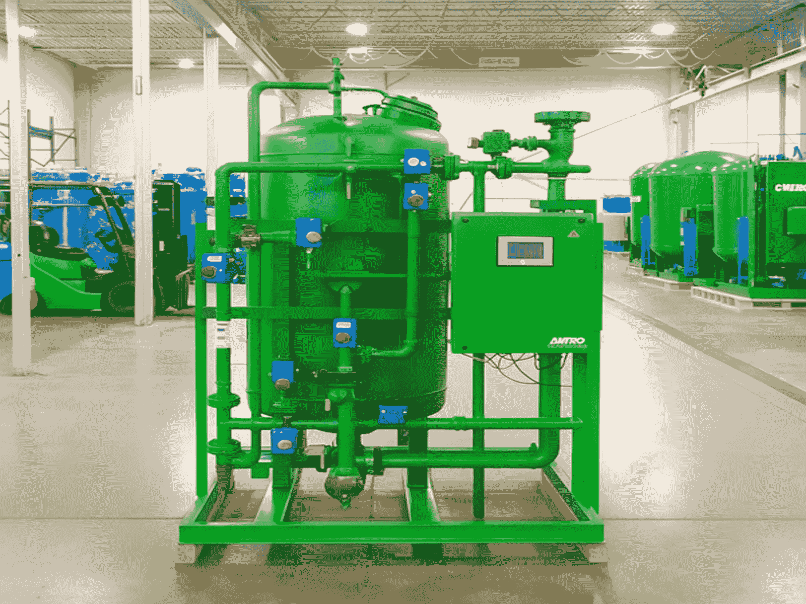
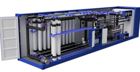
Coalescer Filter very vital for oil removal, for separation of immiscible liquids
Coalescer Filter very vital for oil removal, for separation of immiscible liquids
A coalescer filter is used to separate immiscible liquids or remove liquid droplets from a gas or liquid stream. It works by:
- Capturing very fine dispersed droplets (often in the micron or sub-micron range).
- Merging (“coalescing”) them into larger droplets.
- Allowing these larger droplets to separate under gravity or flow direction change.
Common Uses:
- Oil–water separation (oil removal from produced water, oily wastewater).
- Water removal from hydrocarbon fuels (diesel, kerosene, aviation fuel).
- Liquid removal from natural gas streams.
- Protection of downstream equipment (pumps, turbines, membranes).
Uses of Coalescer Filters in Oil–Water Separation
1. Produced Water Treatment in Oil & Gas
- Upstream Oil Production:
In crude oil production, produced water often contains finely dispersed oil droplets (<10 microns). Gravity separators (API separators) can’t effectively remove these ultra-fine droplets.
Coalescer filters:- Capture sub-micron to few-micron oil droplets.
- Merge them into larger droplets (50–100+ microns) so they rise quickly in downstream separators.
- Reduce oil content to <10 ppm before discharge or reinjection.
- Enhanced Oil Recovery (EOR) systems:
Prevents oil carry-over into reinjection water, protecting reservoir formation from plugging.
2. Refinery Wastewater Treatment
- Desalter Effluent Treatment:
Refinery crude desalters generate oily wastewater streams.
Coalescers improve oil removal before API separators or DAF (Dissolved Air Flotation) units, reducing chemical usage. - Cooling Water Blowdown:
Removes oil films and sheens from cooling tower blowdown streams before discharge to meet environmental limits.
3. Petrochemical & Chemical Plants
- Process Water Cleanup:
Many petrochemical processes generate oily condensate. Coalescers separate the hydrocarbon layer for recovery and reuse. - Cooling and Boiler Feedwater Protection:
Removes oil contamination from process leaks to prevent fouling in heat exchangers and boilers.
4. Power Plants
- Turbine Lube Oil Systems:
Prevents water ingress into lube oil by removing water droplets, or conversely removes oil from water-cooled condenser drain water.
5. Marine Applications
- Bilge Water Treatment:
Ship engine rooms collect bilge water contaminated with fuel oil, lubricating oil, and hydraulic fluids.
Coalescer filters are used in marine Oily Water Separators (OWS) to meet IMO MEPC 107(49) discharge standards (<15 ppm oil overboard). - Deck Drainage Systems:
Prevents overboard discharge of oil during tank washing or fuel transfer.
6. Mining & Industrial Operations
- Heavy Equipment Wash Bays:
Removes diesel and hydraulic oil from wash water before recycling or discharge. - Ore Processing Plants:
Separates flotation reagents and oils from process water streams.
7. Airports & Fuel Handling Facilities
- Stormwater Runoff Treatment:
Removes jet fuel, de-icing fluids, and lubricants from apron and runway drainage water. - Fuel Spill Cleanup:
Emergency treatment of oily water after accidental spills.
Why Coalescer Filters Are Favoured in Oil–Water Separation
- High Efficiency: Can remove very fine droplets down to 0.3 microns.
- Compact Footprint: Requires less space than gravity separators or large settling tanks.
- Low Energy Use: Works on pressure differential; no heat or large pumps required.
- Scalable: Can be designed for small flows (bilge water) to large industrial flows (thousands of m³/hr).
- Compliance: Helps meet strict discharge standards (e.g., <10 ppm for onshore, <15 ppm IMO for ships).
Typical Process Position
Coalescer filters are often installed:
- After primary separation (API separator, CPI separator, or skim tank) to polish the water.
- Before reinjection pumps to protect downhole formations.
- Before biological treatment to prevent oil overloading of microbes.
- Before discharge to surface waters to ensure regulatory compliance.
2. Key Requirements for a Coalescer Filter
A. Performance Requirements
- Separation Efficiency
- Oil–Water: Typically target <10 ppm oil in water at outlet (some designs achieve <1 ppm).
- Gas–Liquid: Remove 99.9% of droplets ≥0.3 microns.
- Fuel–Water: Outlet water content <5 ppm (aviation fuel standards per EI 1581 or API 1581).
- Flow Capacity (Rated Flow)
- Sized for maximum process flowrate without exceeding recommended face velocity.
- Typical liquid–liquid coalescers: 0.1–0.3 m/s face velocity.
- Gas–liquid coalescers: 0.05–0.15 m/s.
- Micron Rating
- Commonly 0.3 to 5 microns for liquid droplets.
- Solid particulate removal capability may also be integrated (dual-stage designs).
- Differential Pressure (ΔP)
- Clean element ΔP: 0.05–0.2 bar.
- Replace element at ΔP of 0.7–1.0 bar or per manufacturer guidance.
B. Construction Requirements
- Housing Material
- Carbon Steel: For non-corrosive hydrocarbon service.
- Stainless Steel 304/316L: For corrosive environments, seawater, or aggressive chemicals.
- Coatings: Epoxy-lined or phenolic-coated for seawater or wastewater.
- Element Media
- Fiberglass: High efficiency, chemical resistant.
- Synthetic fibers: For compatibility with fuels and lubricants.
- Polyester or Polypropylene: For general water/oil service.
- Multi-layer gradient density media for improved droplet capture.
- Sealing
- Buna-N, Viton, EPDM, or fluoropolymer elastomers — chosen based on fluid chemistry and temperature.
- Pressure Rating
- Designed for process operating pressure (e.g., ANSI 150, 300, 600 flanges or equivalent).
- Gas coalescers often rated for 10–150 bar service.
- Temperature Rating
- Select elastomers and media compatible with process temperature (often -20°C to +90°C standard, higher for special designs).
C. Design Features
- Two-Stage Configuration
- Stage 1: Coalescer media (merges fine droplets).
- Stage 2: Separator media (repels coalesced phase and allows clean phase to pass).
- Drainage Provisions
- For separated liquid collection and removal.
- Automatic or manual drains.
- Flow Direction
- Often inside-to-outside for solids removal in first stage, then outside-to-inside for coalescing.
- Ease of Maintenance
- Quick-opening closures (swing bolt, clamp ring) for element replacement.
- Vertical or horizontal vessel orientation depending on site footprint.
- Instrumentation
- Inlet and outlet pressure gauges/transmitters to monitor ΔP.
- Sight glass or level sensor in sump section.
- Optional water-in-fuel detectors (for aviation fuel service).
D. Installation Requirements
- Upstream Filtration: Install particulate filters before coalescer to prevent plugging.
- Flow Conditioning: Avoid high turbulence — use straight pipe runs before unit.
- Drain Connection: For separated phase removal to prevent re-entrainment.
- Vent Connection: To remove trapped gas or air pockets
3. Relevant Standards
- API 12J – Oil–Water Separator Design
- API 1581 / EI 1581 – Aviation Fuel Filter/Separators
- ASME Section VIII – Pressure Vessel Design
- ISO 12500-3 – Compressed Air Filters (Liquid Removal)
- ASTM D3948 – Water Separation Test
4. Typical Specification Table for Procurement
| Parameter | Requirement |
| Service Fluid | Produced water with dispersed oil |
| Inlet Oil Concentration | 200 ppm |
| Outlet Oil Concentration | ≤10 ppm |
| Flowrate | 345 m³/hr |
| Micron Rating | ≤0.3 μm droplets |
| Vessel Design Pressure | 10 bar |
| Vessel Design Temperature | -20°C to +80°C |
| Material of Construction | SS316L |
| Coalescer Element Media | Fiberglass, multi-layer |
| Elastomers | Viton |
| End Connections | ANSI 150 RF |
| Housing Type | Horizontal, two-stage |
| Drain Type | Automatic + manual |
| ΔP Clean | ≤0.15 bar |
| ΔP Dirty | ≥0.7 bar (replacement) |
Coalescer Filter – Engineering Procurement Datasheet
1. General Information
| Item | Specification |
| Type | Horizontal, two-stage coalescer-separator vessel |
| Application | Removal of dispersed oil from produced water / wastewater |
| Standard | API 12J, ASME Section VIII Div. 1 |
| Design Life | 20 years minimum |
| Performance Guarantee | Outlet oil concentration ≤ 10 ppm at design flow |
2. Process Data
| Parameter | Design | Normal | Maximum |
| Flowrate | 345 m³/hr | ___ | ___ |
| Inlet Oil Concentration | 200 ppm | ___ | ___ |
| Outlet Oil Concentration | ≤ 10 ppm | ___ | ___ |
| Fluid Viscosity | ___ cP | ___ | ___ |
| Fluid Temperature | 30°C | ___ | 80°C |
| Fluid Density | Water: 1000 kg/m³, Oil: 850 kg/m³ | ||
| Operating Pressure | 6 bar(g) | ___ | ___ |
| Design Pressure | 10 bar(g) | ||
| Design Temperature | -20°C | +80°C | |
| pH Range | 6.5 – 8.5 |
3. Mechanical Design
| Item | Specification |
| Vessel Orientation | Horizontal |
| Shell Material | SS316L (ASTM A240) |
| Nozzle Flanges | ANSI B16.5, 150# RF |
| Corrosion Allowance | 3 mm |
| Internal Coating | Epoxy phenolic (minimum 300 μm DFT) |
| Closure | Quick-opening, swing bolt type |
| Drain Connection | 2” NPT (Automatic & Manual) |
| Vent Connection | 2” NPT |
| Instrument Connections | ΔP transmitter, level gauge, sight glass |
| Support Type | Saddle support |
| Lifting Lugs | Yes |
4. Coalescer Elements
| Item | Specification |
| Quantity | As per vendor sizing (minimum redundancy: N+1 elements) |
| Flow Direction | Inside-to-outside (coalescing stage), then separator stage |
| Micron Rating | ≤ 0.3 μm droplet capture |
| Media | Multi-layer fiberglass |
| Separator Stage | Teflon-coated hydrophobic mesh |
| Element Outer Shell | Perforated stainless steel |
| Element Length | Standard 40″ or 60″ (vendor to confirm) |
| Seals | Viton (compatible with hydrocarbons) |
| Replacement ΔP | 0.7 bar(g) |
5. Instrumentation & Controls
| Item | Specification |
| Pressure Gauges | Inlet & Outlet, stainless steel, glycerin-filled |
| Differential Pressure Transmitter | 4–20 mA output, HART protocol |
| Level Indicator | Magnetic level gauge + sight glass |
| Automatic Drain | Pneumatic/solenoid actuated |
| Manual Drain | Ball valve, SS316 |
6. Utilities
| Item | Specification |
| Instrument Air | 6–8 bar(g), clean & dry |
| Power Supply | 230 VAC / 50 Hz for solenoid valves |
| Earthing | Vessel & instrumentation earthed per IEC standards |
7. Vendor to Supply
- Vessel with all internals installed.
- Coalescer and separator elements.
- Instrumentation (gauges, transmitters, level indicators).
- Spare element set (for 1 year operation).
- Foundation loading data.
- Installation & O&M manual.
- Performance test certificates.
8. Drawing Requirements
- General arrangement drawing (GA)
- Piping & nozzle orientation drawing
- Internal element layout
- Foundation loading diagram
- Instrument location diagram
9. Testing & Inspection
| Item | Requirement |
| Hydrotest | 1.5 × design pressure per ASME VIII |
| NDE | 100% radiography on longitudinal & circumferential welds |
| Coating Inspection | Holiday test, DFT measurement |
| Performance Test | Witnessed by client at vendor works |
10. Reference Standards
- ASME Section VIII Div. 1 – Pressure Vessel Code
- API 12J – Oil–Water Separator
- ASTM D4286 – Droplet size measurement
- ISO 9001 – QA/QC System
- ISO 12500-3 – Liquid removal from compressed air (relevant testing)


